
The Foundation of M21's Aerodynamic Package - C5 Systems & Austuf
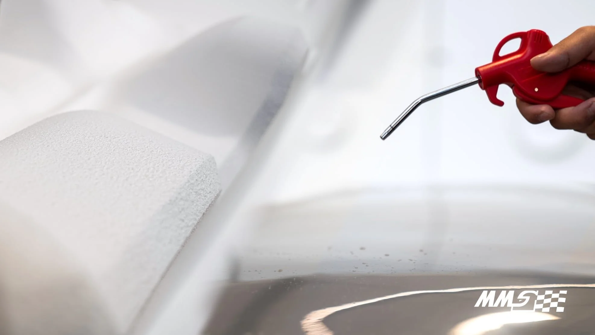
Figure 1: Polystyrene foam mould base and finished mould.
With an extended design period in 2020 as a consequence of the pandemic, a strategic decision saw M21 undergo major concept upgrades from previous years. One of the key aspects of M21’s design is a holistically-developed aerodynamic package which is set to provide an improvement of approximately 60% in CLA (Coefficient of Lift * Area) over our previous vehicle, M19. The introduction of new aerodynamic devices and concepts such as the side wings, tower flaps on the front wing, 3D profiled rear wing mainplane and more, has allowed us to achieve this significant performance upgrade. As a result, we were presented with the challenge of manufacturing our most complex aerodynamic packages yet!
M21’s aerodynamic package required approximately 62 individual moulds which included both smaller 3D printed moulds as well as larger foam moulds. We relied on our long-term sponsors, C5 systems to help manufacture these foam moulds. C5 Systems are equipped with the technology and expertise for rapid CNC machining and hotwire cutting of foam moulds. In previous years we have used hotwire cutting for foam core of wings and flaps as it was a quick and reliable method for 2D extruded profiles. However, when the moulds or inserts cannot be defined by extrusion of a 2D contour itself, we are required to move towards CNC machining. The CNC at C5 Systems can cater to moulds sizes of up to 12m (X) 1.8m (Y) 2.2m (Z). This means that one of M21’s biggest moulds, the undertray keel, can be manufactured in one piece without making it a modular arrangement.
Knowing these manufacturing and tooling capabilities also helps us during the mould design process. This process utilises CAD of the various aerodynamic devices and incorporates allowances for carbon plys, as well as the different coatings to achieve the final offset of the mould surfaces. These coatings include Q-cel resin coat, polyurethane coating and finally, 2K paint. The process is further highlighted in one of our previous blogs linked here. Trimlines are also incorporated as part of the moulds which are used as a guide for cutting the excess carbon off the moulds. Another aspect considered during mould design is its ability to be demoulded. Careful consideration is given to how a part would be removed off the mould without damaging either the part or the mould itself. Design features like negative draft angles, thin and narrow features are avoided.
Austuf is one of our sponsors who play a key role in accelerating the mould manufacturing process by providing us with polyurethane coatings. Austuf coatings are highly advantageous in providing durability and structural protection to decorative and architectural features in commercial properties. However, the same coating can be used in adding the much-needed strength in foam moulds. Polyurethane which forms approximately 1 mm thick layer onto our polystyrene moulds, serves multiple purposes in the manufacturing process. Firstly, this layer helps fill the pinholes which are small craters formed on the surface of the polystyrene moulds when the initial hardener and resin are applied, thus providing a smoother finish and saving the time that would be used in manual sanding these moulds. Secondly, polyurethane acts as a protective coating for our aero mould from resin as contact between the two compounds would cause a chemical reaction which ‘melts’ the polystyrene. Finally, polyurethane strengthens the moulds to resist pressures of up to 100kPa which are experienced when vacuum bag compression as well as the forces experienced during demoulding. This added strength and durability allow the reuse of the moulds to manufacture more parts in the future.
Manufacturing of aerodynamic packages is a major part of each of our vehicle’s development cycles, involving weeks to months of assiduous efforts from team members across departments. With the support of sponsors like C5 Systems and Austuf, we can challenge ourselves to actualize complex aerodynamic packages such as M21’s.

Figure 2: M1’s aerodynamic package